Automated dimensioning functions in 3D CAD software may seem like a great way to save time. With a few clicks of a mouse, dimensions populate across your drawing, and it looks ready to share with manufacturing.
As a contract manufacturer reviews the drawing and prepares for manufacturing, these automated dimensions can end up creating more work. Redundant dimensions, poorly communicated tolerances, and longer inspection times are some of the issues we’ve seen when drawings use what we internally call auto dimensions.
These issues can end up adding more time, effort and back and forth to a project, when manually adding dimensions could have made the process smoother, quicker and more efficient.
Here, we’ll take a closer look at some of the risks of relying on auto dimensioning functions for medical device drawings, and why manually dimensioning drawings can be a better option when you’re working with a contract manufacturer.
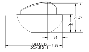 One risk of auto dimensioning is that dimensions may be harder for a contract manufacturer’s team to inspect. In this example, Detail D of a drawing shows the dimension 1.38 anchored to a free-floating point in space. The inspection team will need to perform additional calculations to inspect this dimension. If it was drawn with profile tolerancing, data points could be compared to the model without additional calculations, saving time and expense.
Risk #1: You need more meetings and time to clarify design intent that’s lost through auto dimensions.
Auto dimensions can do many things, but their ability to translate an engineer’s design intent is limited. When design intent is lost, the desired functionality of the part doesn’t come through in the drawing.
The best drawings communicate design intent. Design intent is one of the most important aspects of a medical device’s design, as it gives your contract manufacturer an understanding of how the device will be used and why.
Without this context, it’s more difficult for contract manufacturers to make recommendations to improve the manufacturing process. It also limits their understanding of how a component fits within a larger assembly, if they’re only responsible for one component.
One example is dimensions for a slip fit vs. press fit in an assembly. A customer wanted a loose slip fit on a component, but the assembly’s specs and dimensions looked like a press fit was required. The fit of the device component needed to be reworked to match the design intent of the part.
When an issue like this comes up, the contract manufacturer has to follow up with clarification questions, and extra meetings and communications can add time to a project.
If auto dimensioning saved a few hours of manual dimensioning time, this time savings could easily be lost in additional meetings and communications.
Risk #2: Auto dimensioning often adds redundant dimensions, which may lead to longer inspection times.
Redundant dimensions are a risk of auto dimensioning if an engineer does not manually remove them before sending the drawing to their partner.
When contract manufacturers like Lowell inspect 100 percent of lots to an AQL sample size, every dimension on a drawing has to be inspected and reported on–even the redundant ones.
We can work with customers to skip redundant dimension inspection through a written agreement. However, when that’s not possible, redundant dimensions can quickly increase the amount of time engineering and quality assurance have to spend. It can be especially costly to the OEM when inspections require expensive inspection equipment or are time consuming to program.
Manual dimensioning allows an engineer to avoid the risk of redundant dimensions on the drawing or save the extra step of removing redundancies.
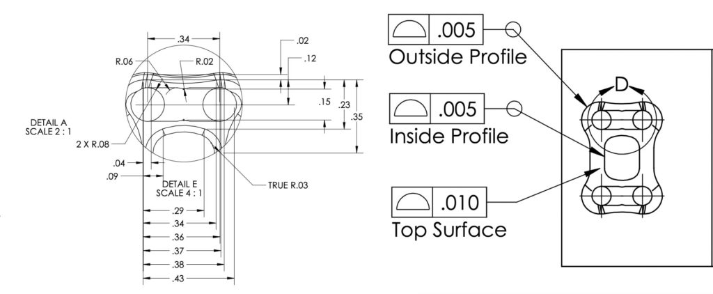
Profile dimensioning can simplify medical device drawings and reduce redundant or confusing dimensions. The image above shows details from a drawing for a plate. Automated dimensioning functions were used to create the dimensions on the left, and redundant dimensions were manually removed. Profile dimensioning was used for the drawing on the right, and more clearly and simply communicates required tolerances for this device.
Risk #3: Automated dimensions use linear dimensioning, which may make inspections more difficult and costly than if profile tolerancing is used.
Auto dimensions rely on linear dimensions and can be set up to automatically add either symmetrical or bilateral dimensions.
This dimensioning approach often means the manufacturing team needs to perform extra calculations to complete inspections, which adds complexity and time. Profile tolerancing would be a better option but requires a manual dimensioning approach.
Profile tolerancing is a method that defines uniform upper- and lower-level boundaries around a physical geometry. Rather than having separate dimensions called out for size, form, orientation, or location–which is needed with linear dimensioning–profile simplifies this into one description. It can reduce clutter on a drawing and also clarify dimensions for the contract manufacturer. (If you’d like to read more about the impact profile tolerancing can have, download our white paper about precision geometrical dimensioning and tolerancing (GD&T) and profile tolerancing.)
For example, auto dimensions may call out the location of radii by connecting tangent edges using linear dimensioning. During inspection, the team will have to run calculations to determine the location of the radii. Instead, if the radii were called out from the center point, a quicker measurement could be made with a manual optical comparator or other vision system. Better yet, if the radii were toleranced as a profile, this could be picked up by a coordinate measuring machine (CMM) or visual measurement system (VMS) and compared directly to the model.
Another common instance where profile could improve inspection is when the walls of a part are tapered at an angle. With linear dimensioning, linear widths are called out to theoretical sharp corners when a radius is applied to the edge. Without profile tolerancing, the quality team needs to calculate the theoretical sharp corner after creating a measurement program. With profile tolerancing, the team could use a CMM or VMS to compare physical points on the part to the model, saving time and expense on calculations.
Risk #4: Parts are poorly toleranced because tolerances default to the title block.
The title block on a drawing shows the default tolerances allowed by a company. If a feature requires different tolerances, the engineer has to add them to the drawing.
With auto dimensioning functions, tolerances are not automatically applied to drawings. If the tolerance isn’t added, the manufacturer will default to the title block. In some cases, this may be fine, and in others it can lead to tolerance stackup issues if a part or feature’s tolerances need to be different.
Accurate tolerance stackups in medical device assemblies are important to make sure all components fit together and work in real life, not only as designed. If a stackup isn’t correct, the parts may not fit together, and the drawing will need to be revised. This can be costly and time consuming.
Manual dimensioning can remove the risk of missing tolerances on a drawing because all dimensions and tolerances are added separately. This can help alleviate issues with inaccurate tolerance stackups.
Weighing the benefits of manual vs. auto dimensioning
A good drawing will answer a lot of a medical device contract manufacturer’s questions on its own. A drawing that’s confusing will always create more questions for machining, engineering, programming, and quality.
In our experience, auto dimensioning can create more questions for contract manufacturers, which can ultimately impact the overall project timeline. Manual dimensioning gives OEMs a better opportunity to share clear design intent and streamline questions on their designs, which makes projects more efficient.
While it may take longer up front and require knowledge of dimensioning schemes, we’ve found the benefits of manual dimensioning outweigh the speed of auto dimensioning.
Interested in learning more? Send us an email at requestinfo@lowellinc.com to talk about how profile tolerancing and manual dimensioning can improve the manufacturing process.